¶ ZECTRIX NOTE4 Developer Kit Development Guide
Hardware scope: This guide applies only to the monochrome ZECTRIX NOTE4 Developer Kit, PCB Version 1.0, with an ESP32-S3 N16R8 and a 4.2-inch 400 x 300 black-and-white e-paper display. NOTE4 and the four-color NOTE4C use different display hardware and firmware images. Do not mix them.
¶ Description
ZECTRIX NOTE4 Developer Kit is a compact ESP32-S3 e-paper development platform for low-power dashboards, information terminals, voice interfaces, NFC applications, and custom embedded projects. It integrates a monochrome e-paper display, rechargeable battery, microphone, speaker, RTC, NFC, three user buttons, and USB Type-C in a finished enclosure.
The developer kit ships with beta demonstration firmware. It is intended for development and evaluation, not as a replacement for the consumer NOTE4 firmware and cloud service.
¶ Start Here
- Official NOTE4 Developer Kit product page
- Buy NOTE4 DevKit from the official ZECTRIX store
- Reference firmware and source code
- Reference project quick start
- Hardware mapping reference
- Prebuilt reference firmware v1.0.0
- ZECTRIX browser firmware updater and download-mode help
¶ Important Notes
- Confirm that the device is a monochrome NOTE4 before flashing.
- PCB Version 1.0 includes NFC. A future international consumer production version may omit NFC, so confirm NFC availability with ZECTRIX customer service before purchase.
- Back up the complete 16 MB factory flash before installing third-party firmware or changing the partition layout.
- Use a USB cable that supports data transfer. A charge-only cable will power the device but will not expose a serial port.
- E-paper keeps the last image without continuous power. This is normal and does not mean the device is still running.
- Display refresh timing and button behavior can vary between firmware projects. The button descriptions below are hardware mappings; application behavior is defined by the installed firmware.
¶ Features
- ESP32-S3 N16R8 with 16 MB Flash and 8 MB PSRAM
- 4.2-inch 400 x 300 monochrome e-paper display with SSD2683 controller
- Full and partial 1 bpp refresh support; full-screen 4 bpp / 16-gray reference support
- 2.4 GHz Wi-Fi and Bluetooth LE 5.0
- Integrated microphone, speaker, audio codec, RTC, NFC, and status LED
- Three physical user buttons plus a recessed RESET pinhole
- USB Type-C power, native USB data, flashing, and serial monitoring
- 2,000+ mAh rechargeable battery
¶ Included
- 1 x ZECTRIX NOTE4 Developer Kit
- 1 x desktop stand
- Beta demonstration firmware installed on the device
- Online schematic, reference source code, and development resources
¶ Typical Applications
- Low-power weather, calendar, task, and status dashboards
- E-paper photo frames and information displays
- Voice-controlled embedded interfaces
- NFC-triggered workflows and smart labels
- ESP32-S3 firmware, display-driver, and power-management development
- Home automation panels and custom IoT terminals
¶ Specifications
| Item | Specification |
|---|---|
| Product | ZECTRIX NOTE4 Developer Kit / NOTE4 Devkit |
| PCB version | 1.0 |
| Main controller | ESP32-S3 N16R8 |
| Flash / PSRAM | 16 MB Flash / 8 MB PSRAM |
| Wireless | 2.4 GHz Wi-Fi, Bluetooth LE 5.0 |
| Display | 4.2-inch black-and-white e-paper |
| Resolution | 400 x 300 pixels |
| Display controller | SSD2683 |
| Audio | ES8311 codec, microphone, speaker |
| RTC | PCF8563 |
| NFC | NT3H2111 / NT3H2211 family interface |
| Controls | Up, Down / Power, BOOT / Confirm, recessed RESET |
| USB | USB Type-C for power, native USB data, flashing, and serial |
| Battery | 2,000+ mAh rechargeable battery |
| Dimensions | 97 x 97 x 8.75 mm, including magnetic back cover |
| Enclosure | ABS |
¶ Controls and Ports
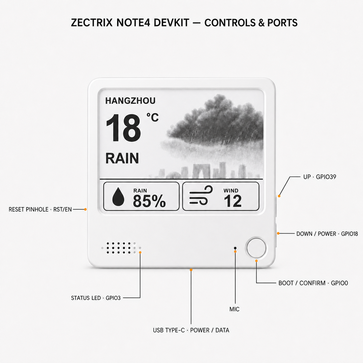
The control diagram is shown at the top of this guide. When the display faces you:
| Physical control or port | Hardware signal | Notes |
|---|---|---|
| Right-side upper button | GPIO39 | Up; active low |
| Right-side lower button | GPIO18 | Down / power-related input; active low |
| Front circular button | GPIO0 | BOOT / Confirm; active low |
| Left-side RESET pinhole, level with Down | ESP32-S3 EN / RST | Press briefly to reset the controller |
| Bottom-center USB Type-C port | USB D- GPIO19, USB D+ GPIO20 | Power, native USB data, flashing, and serial |
¶ Power and Reset
GPIO17 controls the board power-hold circuit. Firmware that uses battery power must keep the power latch in the required state after startup. GPIO18 is also connected to the Down / Power button, so shutdown behavior is firmware-dependent.
The recessed pinhole on the left side is the hardware RESET input. It drives the ESP32-S3 EN / RST signal and does not erase firmware.
¶ Enter ESP32-S3 Download Mode
Most computers can connect to the NOTE4 Developer Kit without pressing any buttons. If the serial connection or flashing tool cannot detect the device:
- Keep the USB Type-C data cable connected.
- Press and hold the circular BOOT / Voice button on the front (GPIO0).
- While holding BOOT, press the recessed RESET pinhole on the left side once.
- Release BOOT.
- Reconnect from the flashing tool and select the newly detected ESP32-S3 serial device.
This manually places the ESP32-S3 in ROM download mode. Chrome or Edge on desktop is recommended for the ZECTRIX browser firmware updater. The reference project's serial monitor uses 115200 baud.
¶ Pin Map
¶ E-Paper Interface
| Function | ESP32-S3 GPIO |
|---|---|
| E-paper power enable | 6 |
| BUSY | 8 |
| RESET | 9 |
| DC | 10 |
| CS | 11 |
| SCK | 12 |
| MOSI / SDA | 13 |
¶ Buttons, LED, Battery, and Charging
| Function | ESP32-S3 GPIO | Notes |
|---|---|---|
| BOOT / Confirm | 0 | Active low; boot-strapping pin |
| Charge complete / standby | 1 | STDBY_H |
| Charging status | 2 | CHRG_L |
| Status LED | 3 | Green LED |
| Battery voltage ADC | 4 | Battery voltage through resistor divider |
| RTC interrupt | 5 | PCF8563 interrupt |
| NFC field detect | 7 | NT3H field-detect signal |
| Power hold | 17 | Board power latch control |
| Down / Power button | 18 | Active low |
| NFC power control | 21 | NFC power-down / enable control |
| Up button | 39 | Active low |
¶ Audio Interface
| Function | ESP32-S3 GPIO |
|---|---|
| I2S MCLK | 14 |
| I2S BCLK / SCLK | 15 |
| Codec DOUT / ESP32 RX | 16 |
| I2S LRCK / WS | 38 |
| Audio power enable | 42 |
| Codec DIN / ESP32 TX | 45 |
| Speaker amplifier control | 46 |
¶ I2C Peripherals
| Signal / peripheral | Value |
|---|---|
| I2C SDA | GPIO47 |
| I2C SCL | GPIO48 |
| PCF8563 RTC address | 0x51 |
| NT3H NFC address | 0x55 |
¶ USB and UART
| Function | ESP32-S3 GPIO |
|---|---|
| USB D- | 19 |
| USB D+ | 20 |
| UART0 TX | 43 |
| UART0 RX | 44 |
All GPIO signals use 3.3 V logic. Do not apply 5 V directly to a GPIO.
¶ Schematic
The English edition replaces the Chinese functional labels and title-block captions while preserving the original circuit content and PCB Version 1.0 identification.
¶ Software Development
¶ ESP-IDF Reference Project
The public reference project targets ESP-IDF 5.4 or later and is licensed under the MIT License.
git clone https://github.com/itopinion/zectrix-note4-epd-demo.git
cd zectrix-note4-epd-demo
idf.py set-target esp32s3
idf.py build
idf.py -p /dev/cu.usbmodemXXXX flash monitor
Replace /dev/cu.usbmodemXXXX with the serial port detected on your computer. On Windows, use the corresponding COM port. Press Ctrl + ] to exit the serial monitor.
¶ Prebuilt Reference Firmware
The v1.0.0 release provides zectrix-note4-epd-demo-v1.0.0.bin, a merged image written at flash address 0x0.
| Item | Value |
|---|---|
| Release | v1.0.0 |
| Filename | zectrix-note4-epd-demo-v1.0.0.bin |
| Flash address | 0x0 |
| SHA-256 | a3649af0692987bd21ec815b224166c36bd91aa266657c7628a393cad1318072 |
This reference image is only for the monochrome NOTE4 hardware profile. It is not the consumer NOTE4 firmware and is not compatible with NOTE4C.
¶ Official Component Documents
- ESP32-S3 datasheet - Espressif
- PCF8563 RTC datasheet - NXP
- ES8311 product brief - Everest Semiconductor
- ES8311 ESP-IDF component - Espressif Component Registry
The display controller used by NOTE4 is SSD2683. A public manufacturer-hosted SSD2683 datasheet is not currently linked here; use the NOTE4 schematic and the public reference driver's API and source code as the development reference.
¶ Support Boundary
The NOTE4 Developer Kit is a development device. Third-party firmware, custom partition layouts, and hardware modifications are the developer's responsibility. Keep a verified factory-flash backup and record the exact firmware filename, flash address, and checksum before installation.