¶ ZECTRIX NOTE4C Devkit Development Guide
Hardware scope: This guide applies only to the four-color ZECTRIX NOTE4C Devkit, PCB Version 1.0, with an ESP32-S3 N16R8 and a 4.2-inch 400 x 300 black, white, red, and yellow e-paper display. Except for the display panel and its refresh behavior, NOTE4C uses the same controller board, controls, audio, power system, USB interface, and enclosure as the monochrome NOTE4 Devkit. Their display firmware images are not interchangeable.
¶ Description
ZECTRIX NOTE4C Devkit is an assembled ESP32-S3 four-color e-paper development platform for low-power information displays, electronic labels, photo cards, status panels, and custom embedded projects. It combines the display, controller board, rechargeable battery, microphone, speaker, RTC, NFC, physical controls, USB Type-C, magnetic back, and finished enclosure in one device.
NOTE4C is an open development device. It does not include the ready-to-use NOTE4 consumer firmware, official NOTE4 AI voice task experience, or NOTE4 cloud service. A public reference firmware is provided for basic Wi-Fi setup, image transfer, four-color display testing, and further development.
¶ Start Here
- Official NOTE4C Devkit product page
- Buy NOTE4C DevKit from the official ZECTRIX store
- NOTE4C reference firmware and source code
- Firmware repository README
- Download the ready-to-flash NOTE4C merged firmware
- ZECTRIX browser firmware updater and download-mode help
- Monochrome NOTE4 Devkit development guide
¶ Important Notes
- Confirm that the device is a four-color NOTE4C before flashing. Never install a monochrome NOTE4 firmware image on NOTE4C.
- PCB Version 1.0 includes NFC. A future international consumer production version may omit NFC, so confirm NFC availability with ZECTRIX customer service before purchase.
- Back up the complete 16 MB factory flash before installing third-party firmware or changing the partition layout.
- Use a USB cable that supports data transfer. A charge-only cable will power the device but will not expose a serial port.
- A four-color full-screen refresh normally takes more than 10 seconds. Flickering, brief color inversion, or visible pigment movement during refresh is normal.
- E-paper keeps the last image without continuous power. A visible image does not mean that the device is still running.
- The button actions in the prebuilt reference firmware are described later in this guide. Other firmware projects can assign different application behavior to the same hardware inputs.
¶ Features
- ESP32-S3 N16R8 with 16 MB Flash and 8 MB PSRAM
- 4.2-inch 400 x 300 black, white, red, and yellow e-paper display
- SSD2683 display controller and 2 bpp BWRY output
- 2.4 GHz Wi-Fi and Bluetooth LE 5.0
- Integrated microphone, speaker, ES8311 audio codec, PCF8563 RTC, NFC, and status LED
- Three physical user buttons plus a recessed RESET pinhole
- USB Type-C power, native USB data, flashing, and serial monitoring
- 2,000+ mAh rechargeable battery
¶ Included
- 1 x ZECTRIX NOTE4C Devkit
- 1 x desktop stand
- Assembled four-color display, controller board, battery, enclosure, buttons, and magnetic back
- Online reference firmware, source code, and development resources
¶ Typical Applications
- Four-color weather, calendar, task, and status dashboards
- Electronic labels and low-frequency information panels
- E-paper photo cards and gallery displays
- Voice-enabled ESP32-S3 interfaces
- NFC-triggered workflows and smart labels
- Four-color display-driver, power-management, and embedded UI development
- Home automation panels and custom IoT terminals
¶ Specifications
| Item | Specification |
|---|---|
| Product | ZECTRIX NOTE4C Devkit |
| PCB version | 1.0 |
| Main controller | ESP32-S3 N16R8 |
| Flash / PSRAM | 16 MB Flash / 8 MB PSRAM |
| Wireless | 2.4 GHz Wi-Fi, Bluetooth LE 5.0 |
| Display | 4.2-inch four-color e-paper |
| Display colors | Black, white, red, and yellow |
| Resolution | 400 x 300 pixels |
| Display controller | SSD2683 |
| Display format | 2 bpp BWRY |
| Refresh | Full-screen refresh; normally more than 10 seconds per image |
| Audio | ES8311 codec, microphone, speaker |
| RTC | PCF8563 |
| NFC | Included on PCB Version 1.0 |
| Controls | Up, Down / Power, BOOT / Confirm, recessed RESET |
| USB | USB Type-C for power, native USB data, flashing, and serial |
| Battery | 2,000+ mAh rechargeable battery |
| Dimensions | 97 x 97 x 8.75 mm, including magnetic back cover |
| Enclosure | ABS |
¶ Controls and Ports
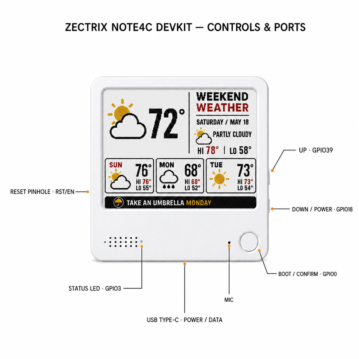
The control diagram is shown at the top of this guide. When the display faces you:
| Physical control or port | Hardware signal | Notes |
|---|---|---|
| Right-side upper button | GPIO39 | Up; active low |
| Right-side lower button | GPIO18 | Down / power-related input; active low |
| Front circular button | GPIO0 | BOOT / Confirm; active low; boot-strapping pin |
| Small front pinhole beside the circular button | Microphone input | Connected through the ES8311 audio path |
| Isolated hole at the right end of the speaker-hole row | GPIO3 | Status LED |
| Left-side RESET pinhole, level with Down | ESP32-S3 EN / RST | Press briefly to reset the controller |
| Bottom-center USB Type-C port | USB D- GPIO19, USB D+ GPIO20 | Power, native USB data, flashing, and serial |
¶ Power and Reset
GPIO17 controls the board power-hold circuit. Firmware that runs from the battery must keep the power latch in the required state after startup. GPIO18 is also connected to the Down / Power button, so power-on, shutdown, and long-press behavior depend on the installed firmware.
The recessed pinhole on the left side is the hardware RESET input. It drives the ESP32-S3 EN / RST signal and does not erase firmware or user data.
¶ Enter ESP32-S3 Download Mode
Most computers can connect to the NOTE4C Devkit without pressing any buttons. If the browser updater or esptool cannot detect the device:
- Keep the USB Type-C data cable connected.
- Press and hold the circular BOOT / Confirm button on the front (GPIO0).
- While holding BOOT, press the recessed RESET pinhole on the left side once.
- Release BOOT.
- Connect again and select the newly detected ESP32-S3 serial device.
This manually places the ESP32-S3 in ROM download mode. A normal restart returns the device to regular operation.
¶ Pin Map
¶ E-Paper Interface
The controller-side e-paper signals are shared with NOTE4, but the installed panel and firmware configuration are different.
| Function | ESP32-S3 GPIO |
|---|---|
| E-paper power enable | 6 |
| BUSY | 8 |
| RESET | 9 |
| DC | 10 |
| CS | 11 |
| SCK | 12 |
| MOSI / SDA | 13 |
¶ Buttons, LED, Battery, and Charging
| Function | ESP32-S3 GPIO | Notes |
|---|---|---|
| BOOT / Confirm | 0 | Active low; boot-strapping pin |
| Charge complete / standby | 1 | STDBY_H |
| Charging status | 2 | CHRG_L |
| Status LED | 3 | Green LED |
| Battery voltage ADC | 4 | Battery voltage through resistor divider |
| RTC interrupt | 5 | PCF8563 interrupt |
| NFC field detect | 7 | NFC field-detect signal |
| Power hold | 17 | Board power latch control |
| Down / Power button | 18 | Active low |
| NFC power control | 21 | NFC power-down / enable control |
| Up button | 39 | Active low |
¶ Audio Interface
| Function | ESP32-S3 GPIO |
|---|---|
| I2S MCLK | 14 |
| I2S BCLK / SCLK | 15 |
| Codec DOUT / ESP32 RX | 16 |
| I2S LRCK / WS | 38 |
| Audio power enable | 42 |
| Codec DIN / ESP32 TX | 45 |
| Speaker amplifier control | 46 |
¶ I2C Peripherals
| Signal / peripheral | Value |
|---|---|
| I2C SDA | GPIO47 |
| I2C SCL | GPIO48 |
| PCF8563 RTC address | 0x51 |
| NFC interface address | 0x55 |
¶ USB and UART
| Function | ESP32-S3 GPIO |
|---|---|
| USB D- | 19 |
| USB D+ | 20 |
| UART0 TX | 43 |
| UART0 RX | 44 |
All GPIO signals use 3.3 V logic. Do not apply 5 V directly to a GPIO.
¶ Schematic
NOTE4C PCB Version 1.0 uses the same controller board and peripheral mapping as the NOTE4 Devkit shown in this schematic. The installed e-paper panel and required display firmware configuration are different; use the NOTE4C four-color panel setting described below.
¶ Flash the Reference Firmware
Reference project: This guide uses NOTE4C Four-Color Reference Firmware, maintained by LazyYoun. It is distinct from the monochrome NOTE4 16-gray Gallery (4BP). Compare the NOTE4C firmware options.
¶ Ready-to-Flash Merged Image
The following merged image belongs to the previously published NOTE4C open-source reference firmware line. The simple operating instructions in the next section refer to this image.
| Item | Value |
|---|---|
| Download | NOTE4C merged firmware |
| Filename | notellm-2bp-v6.5.9-2bp-3fbbabb-20260705-mergebin.bin |
| Target | ESP32-S3 NOTE4C four-color hardware |
| File type | Merged firmware image |
| Flash address | 0x0000 |
| File size | 3,054,752 bytes |
| SHA-256 | 26f209f7cdea8f62bff73f2e877e3ab421917c17497a2a23340129c6ef43fc36 |
Verify the filename, file size, and checksum before flashing. Do not write this image to a monochrome NOTE4.
¶ Recommended: ZECTRIX Browser Firmware Updater
The ZECTRIX Firmware Updater installs a local .bin file through a direct USB connection. The firmware file is read locally in the browser and is not uploaded to ZECTRIX.
- Open the updater in a current desktop version of Chrome or Edge. Safari and Firefox do not provide the required Web Serial connection.
- Connect the NOTE4C Devkit directly to the computer with a USB data cable.
- Click Connect device and select the ZECTRIX / ESP32-S3 USB serial device.
- Select the downloaded merged
.binfirmware file. - Choose whether to keep device settings. The recommended option backs up the settings partition and restores it after installation. Clear it when you intentionally want a clean configuration.
- Review the firmware filename and confirm that the write address is
0x0000. - Click Install firmware and keep the cable connected until installation completes.
- Allow the updater to restart the device. If necessary, use Restart again after the installation result appears.
If the device cannot connect, use the BOOT / RESET download-mode sequence above and click Connect device again.
¶ Alternative: esptool
Install or update esptool:
python3 -m pip install --upgrade esptool
Run the following command from the directory containing the firmware file:
python3 -m esptool \
  --chip esp32s3 \
  --port /dev/cu.usbmodemXXXX \
  --baud 460800 \
  write-flash 0x0 notellm-2bp-v6.5.9-2bp-3fbbabb-20260705-mergebin.bin
Replace the serial port with the port detected on your computer. On Windows, use the corresponding COM port and replace python3 with python if required. The merged image must be written to 0x0.
¶ Using the Prebuilt Reference Firmware
The behaviors in this section apply to the ready-to-flash image listed above. A custom build or a later repository revision may behave differently.
¶ Button Controls
- Short-press Up: previous item or previous page.
- Short-press Down: next item or next page.
- Short-press BOOT: confirm.
- Double-press Up: open quick page switching.
- Press and hold Down for about one second: open Settings.
- Press and hold Up and Down together for about one second: enter Wi-Fi setup.
- Press and hold BOOT on the Gallery page: enter hotspot image-transfer mode.
- Press and hold BOOT on the hotspot image-transfer page: exit image-transfer mode.
- Press BOOT after deep sleep: wake the device.
Wait for each four-color refresh to complete before pressing another button.
¶ First-Time Wi-Fi Setup
When no network is saved, the firmware normally enters setup mode automatically. If it does not:
- Press and hold Up and Down together for about one second.
- Wait for the screen to show Wi-Fi setup.
- On a phone, connect to the open hotspot whose name begins with
ZecTrix. - If the setup page does not open automatically, visit
http://192.168.4.1. - Select a 2.4 GHz Wi-Fi network, enter its password, and save.
ESP32-S3 cannot connect to a network that provides only 5 GHz Wi-Fi. If the Gallery page still shows an old connection state after successful setup, press RESET once or switch to another page and return.
¶ Upload Four-Color Images from a Phone
- Open Gallery with the Up and Down buttons.
- Press and hold BOOT to enter hotspot image-transfer mode.
- Connect the phone to:
Network: InkScreen-AP
Password: 12345678
- Open
http://192.168.4.1in the phone browser. - Select the 2 BP Four Color conversion mode.
- Select a JPG, PNG, or other supported image and check the 400 x 300 preview.
- Send the image, then choose Display if you want to show it immediately.
The browser scales the image and converts it to black, white, red, and yellow. A separate BIN conversion is not required.
Do not confuse the two hotspots:
ZecTrix...: first-time home Wi-Fi setup; no password by default.InkScreen-AP: Gallery image transfer; password12345678.
¶ Upload Images over the Local Network
After NOTE4C connects to the home network:
- Open Settings on the device.
- Enable the local-network service.
- Note the IP address displayed on the screen.
- From a phone or computer on the same network, open
http://device-ip/, replacingdevice-ipwith the displayed address.
The local page can upload images, preview the four-color conversion, display and manage images, and configure a slideshow. The DHCP address can change, so use the address currently shown on the device.
¶ Software Development
¶ Open-Source Project
The public LazyYoun/youn-ink-fourcolor-firmware repository uses the 2bp branch as its default branch and is published under the MIT License. It contains ESP-IDF firmware plus optional server and management components.
git clone https://github.com/LazyYoun/youn-ink-fourcolor-firmware.git
cd youn-ink-fourcolor-firmware/firmware
The current repository documentation uses an ESP-IDF 6.0 environment. Activate your ESP-IDF environment, then build the firmware:
idf.py set-target esp32s3
idf.py menuconfig
idf.py build
idf.py -p /dev/cu.usbmodemXXXX flash monitor
Replace /dev/cu.usbmodemXXXX with the serial port detected on your computer. On Windows, use the corresponding COM port. Press Ctrl + ] to exit the serial monitor.
¶ Select the NOTE4C Panel
The four-color panel is the repository's default ZECTRIX panel configuration. In idf.py menuconfig, confirm:
ZecTrix EPD panel type
└── 4-color BWRY SSD2683 EPD
Corresponding configuration:
CONFIG_ZECTRIX_EPD_PANEL_4COLOR_SSD2683=y
Do not select the 1 bpp black-and-white panel when building for NOTE4C.
¶ Repository Scope
The repository is an evolving reference project rather than the NOTE4 consumer firmware. It currently includes firmware UI and display code, AP image transfer, optional Python server components, and image / device management functions. Read the current README and source before enabling external services, APIs, OTA endpoints, or custom partitions. Do not commit .env files, API keys, Wi-Fi credentials, build output, logs, or local databases.
¶ Official Component Documents
- ESP32-S3 datasheet - Espressif
- PCF8563 RTC datasheet - NXP
- ES8311 product brief - Everest Semiconductor
- ES8311 ESP-IDF component - Espressif Component Registry
The display controller used by NOTE4C is SSD2683. A public manufacturer-hosted SSD2683 datasheet is not currently linked here; use the NOTE4C schematic mapping, panel configuration, and public driver source as the development reference.
¶ Support Boundary
NOTE4C is a development device. Third-party firmware, custom partition layouts, server deployment, external API services, and hardware modifications are the developer's responsibility. Keep a verified 16 MB flash backup and record the exact firmware filename, flash address, and checksum before installation. If you suspect a hardware fault, contact ZECTRIX support with the device model, PCB version, firmware filename, reproduction steps, and photographs or video of the behavior.